
Building a Switching layout, Part I
A foam project layout.
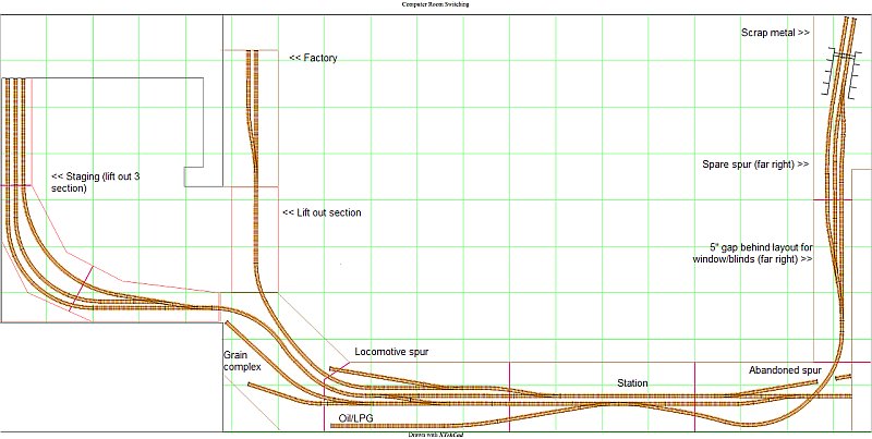
I've started buying track for the Christmas layout, and at the same time I'm going to build myself a much larger switching layout here in my computer room. So far I've developed a track plan, which is on V1.6 now.
This will be a multi-part article, in several sections of the site, from bench work, to wiring, DCC, scenery, structures, and more. The whole layout will be foam based, with wood legs. I'll describe my construction method for both here.
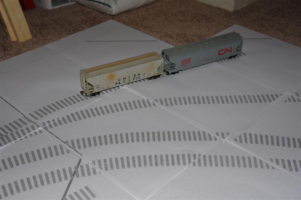
Step one, printing the track plan from XtrkCad. I opted to to a 1:1 print of the plan to get it all to fit the way the plan shows.
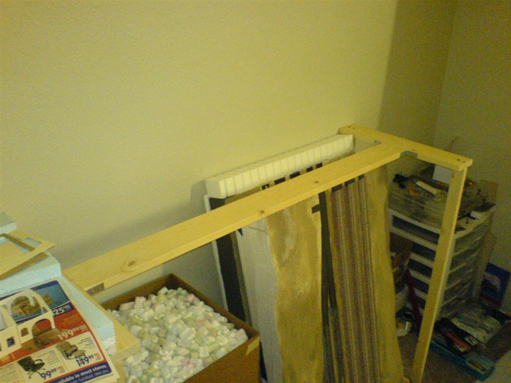
Step two, building the module legs. I've opted for some very light weight construction for a few reasons. One, as its a modular layout, I can move it when I move. The modules being all foam (no wood frame) make it easier to transport. To support something so light, the legs can be very basic. Here, they're 1"x2" stock, with a 1"x2" base, and a 1"x4" platform on the top. The legs will be positioned at the joining points of the module, thus why I've opted for a 1"x4" on the top. They're strung together with a 1"x4" along the rear, to minimize movement.
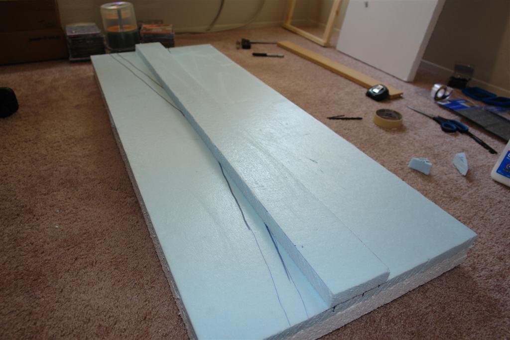
Step three, building the foam modules does not have to be complex. I've opted for a more robust design, fashioned like a deck, or a floor would be in house. Basic Construction of an All Foam Module
Step four, connecting the modules is accomplished with 1/4" bolts and wing nuts, secured through Woodland Scenics end plates. I chose these plates because they're readily available, and should be secure enough to not rip through the foam frame. I'll check to see if there's a cheaper option at the local home improvement stores however. Track will but up to the edges of the modules, be cut at 90 degrees to itself, and connected at each joint with a rail joiner, to help smooth the joint and provide improved electrical flow.
Step five, wiring is another story. In this case, each module will include a feeder wire, and at the ends of the module, some in-line connectors. The layout will be wired for DCC, and all switches will be manually operated from a switch stand, so there will be no need to wire motors. I've chose this, because I'm shy of moving modules with a motor hanging from the bottom, and the excessive work to remove & replace the motors is not worth it.
Step six, now that the basics are built, I need to get the track plan onto the foam. There's a few ways, one of which includes just gluing the plan to the foam. I'm adding 1" risers to the whole of the layout (with a few grades included), so tracing is the better option for me. I'll place the track plan in the foam, with carbon paper under it, and trace the plan onto the foam. After adding the risers, and working out the terrain, I can re-do this step to make sure I get no kinks in the plan.
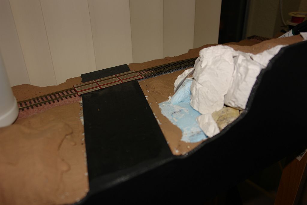
Step seven, adding the risers, and surrounding terrain is not as hard as it would seem. I have a surplus of Woodland Scenics plaster cloth, so I'll be using this, along with some of their foam risers. Using Risers on Your Layout
Step eight, step on over to Building a Switching layout, Part II to see how I add track & scenery.
In 2012, I moved, and though I had planned to move the layout, I ended up dismantling, and throwing away the vast majority of this layout. In 2018, I started another, smaller, more mobile layout after another move. The side effect of living in apartments.
©2007/2020, Josh Baakko, https://www.modelrailroadtips.com