Building the Benchwork
An article by Stephen McCallum aka fsm1000. This is an authorized repost of his article, which was originally posted on his website which he is now planning to close.
Now we get to the point of actually building the thing. It was at this point I found out how expensive wood has gotten. So for the lower bench part I used 2x4's instead of the original 1x6's. I saved about 50 dollars overall by doing this.
So now you see once more the beauty of making a model of your model before you build. In this way I was able to substitute without major problems. I knew the dimensions and all that, so it was easy.
If you wish to, you can make another model. You waste nothing because the time invested will only sharpen your skills further.
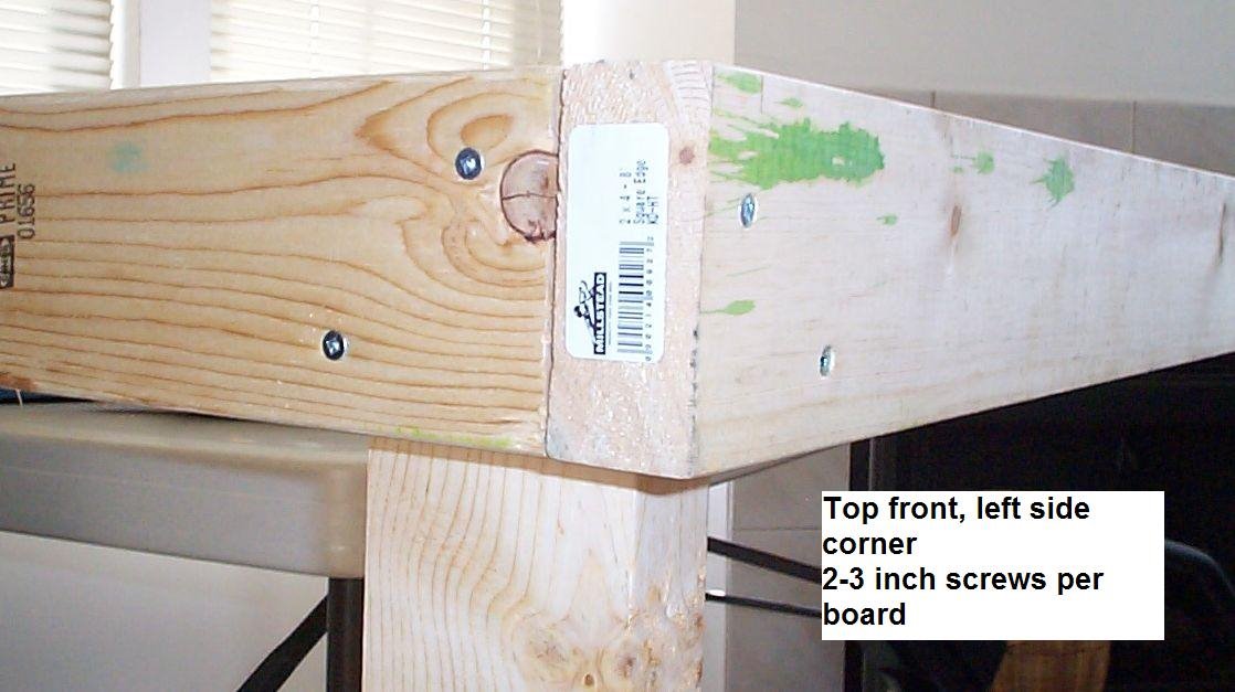
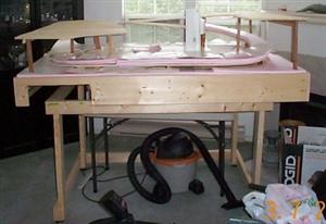
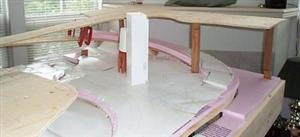
As you can see in the first and second photo,

I put two 3 inch screws into each leg bottom. I predrilled first of all to prevent splitting. I used number 8 screws. You can use 8 or 10 but I don't recommend number 6 because it will be too thin to handle the weight over the long haul. We are not gluing the bottom. This way when we move we can disassemble it and take it with us.
Also the top comes off and can be put on it's end on a trolley and fit through most doors. Most door are 6 foot 6 inches high and 30 inches wide at least. This will fit through that easily.
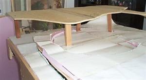
In the 3rd picture you see the top left side. I again used 3 inch screws. 2 for each piece.
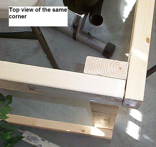
The 4th picture is the same from only a top view.
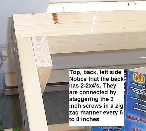
Ok in the 5th picture you will see that I put two 2x4's together. We are holding the top to the bottom with hinges so this will be the place where the hinges connect to. I screwed in 3 inch screws staggered in a zigzag every 6 to 8 inches about along the whole length. Also this too was attached to the legs and cross members ahead of time by two screws each in the legs and cross members.
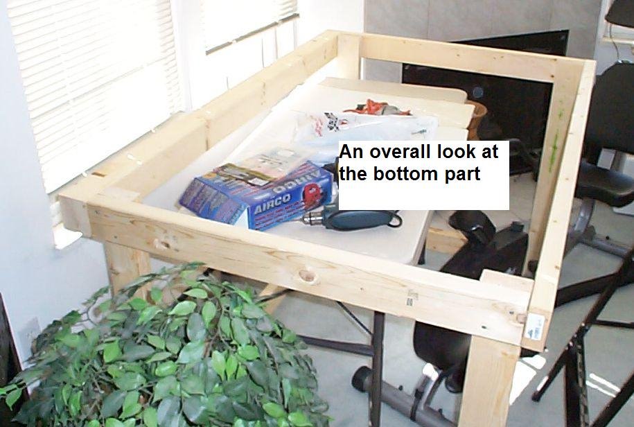
The 6th photo gives you an overall view of the bottom bench. This has castor's on it as well for ease of movement. When not used it sits against one wall, or in my case a window.
The 7th photo is the beginning of the frame. You can see that two 2x4's are glued and screwed on to the 1x8 at the back there. The 2x4 is on an angle is on an angle because it needs to bypass the turntable and switches (turnouts) above it. Also the river on the far side. All of the top parts are glued as well as screwed in place. The bottom part is only screwed so it can come apart later.
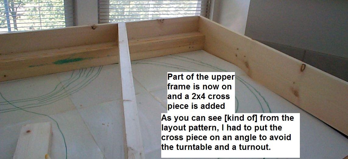
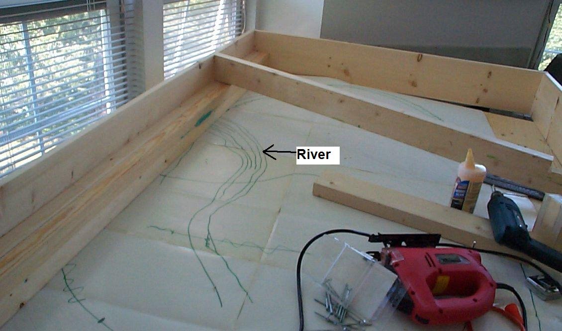
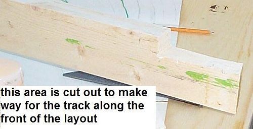
Photo 9 shows a cut out in the 2x4 near the front. This is done to accommodate the track at the front of the layout which is lower (by an inch) then the rest of the layout.
The 10th photo shows the two 2x4's connected to the 1x8.
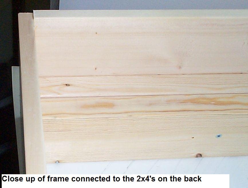
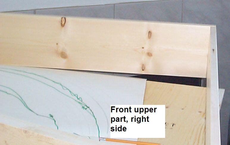
Photo 11 shows the front right side.
Picture 12 shows one of the three hinges I put on this. I used brass door hinges. This gives it stability and safety and smooth as butter. With the front pieces glued in place (explained later) and two pieces glued on the back ends (see right side of photo 12) to prevent the top from falling through (because the bottom frame is smaller that the top part), this makes adding the hinges as simple as laying them down on the board and screwing in the screws. I ALWAYS pre-drill my holes on this to prevent the wood from splintering. Even for the hinges.
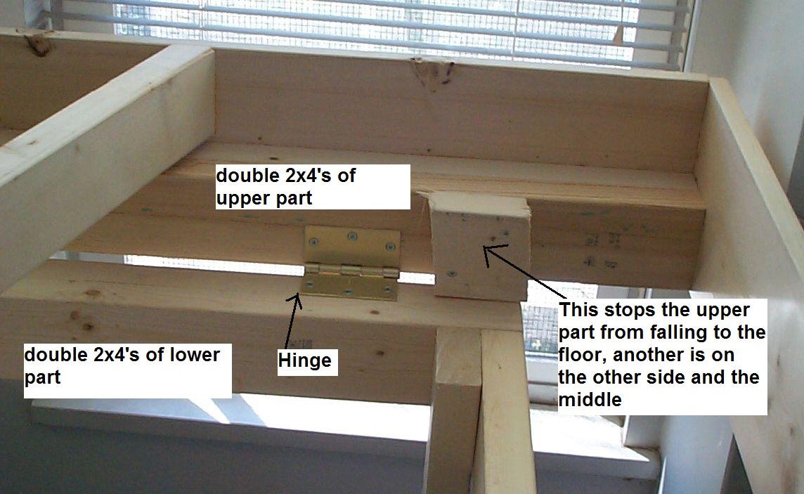
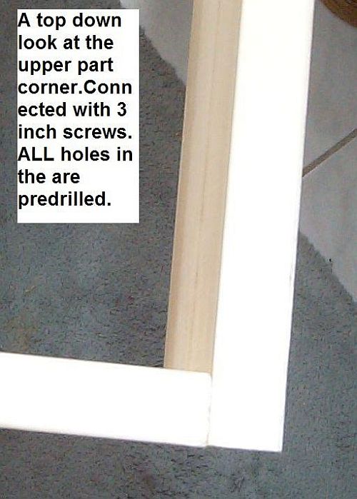
Photo 13 shows a top down look at one the frames corners. Again, pre-drilled, glued and screwed with 3 inch screws.
On the 14th Photo you can see the angled 2x4. and an overview of the upper and lower parts.
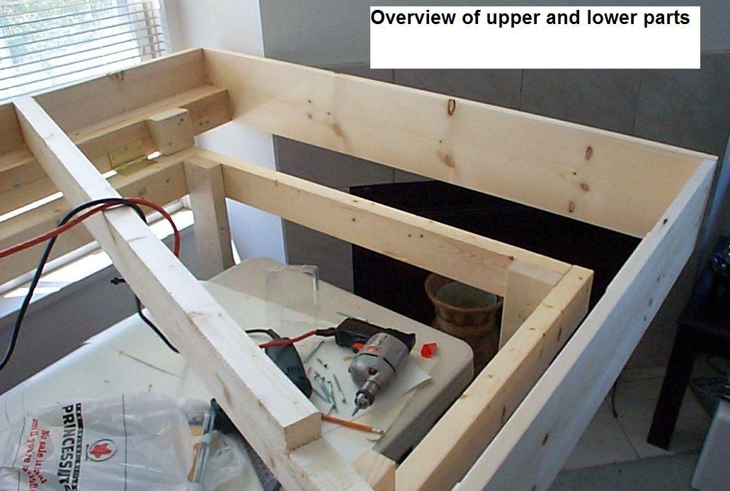
A friend cut the angled 2x4 for me and unfortunately cut it almost 2 inches short. After praying about it, I got a picture in my head how to fix it and so I did it by gluing and screwing the top end then screwing and gluing a piece of 2x4 on the bottom end and pushing hard to make them meet. And gluing and screwing them together. With glue and 3 inch screws it works. Stuff happens, oh well.
On the 15th Photo you can see the other 2x4 brace. It was placed at 20 inches in from the edge and straight across the width. Notice too the slim pieces of wood under the two cross braces. This hold the front up. With the hinges on the back, the front will lean down so these two pieces are needed and really simple. Just cut and glue and set. Wait till it dries and it is done. I glued them to the top piece for convenience.
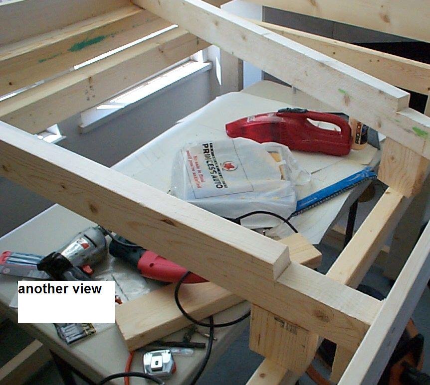
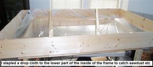
Photo 16 shows how I added a drop cloth to minimize the sawdust to come. After all this is being done in the living room.
Photos 17 and 18 show the beginning of the cuttings.
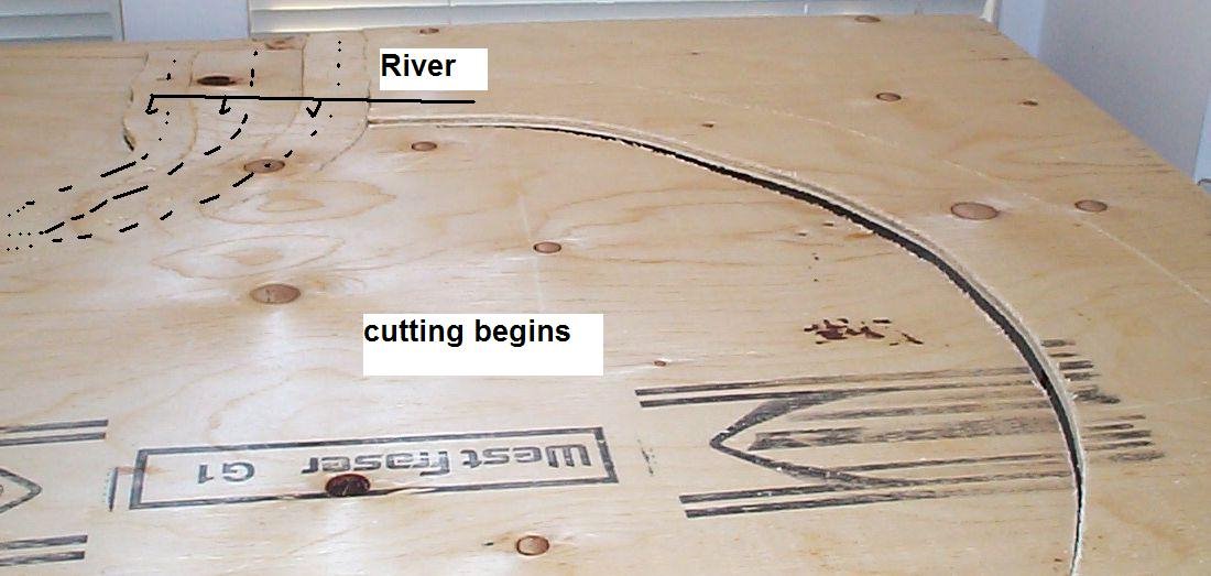
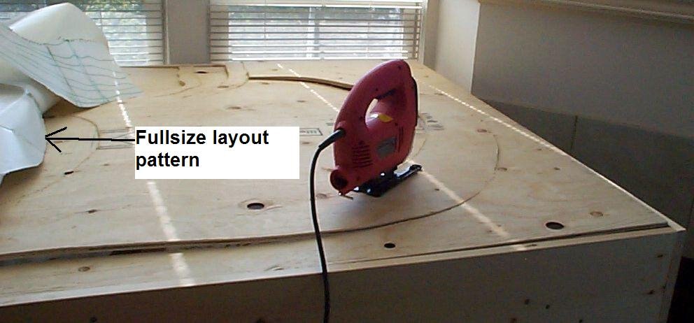
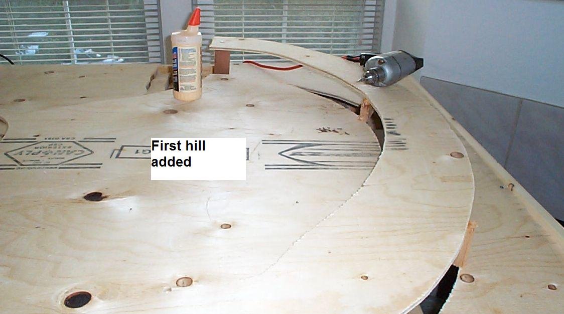
Photo 19 shows the start of the hill.
Photos 20, 21 and 22 shows the foam being added.
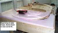
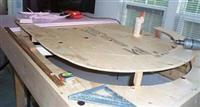
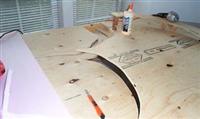
The foam was 1/2 inch thick and 2 feet by 8 feet in size. I cut them all in half and added them that way. It made it easier to cut into the right shapes.
Photos 23 and 24 shows all the foam and the template (or pattern) added.
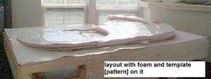
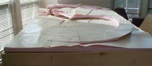
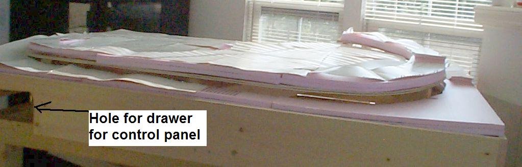
Photo 25 also shows part of the hole for the drawer that will contain the control panel. I messed it up pretty good as you will see later.
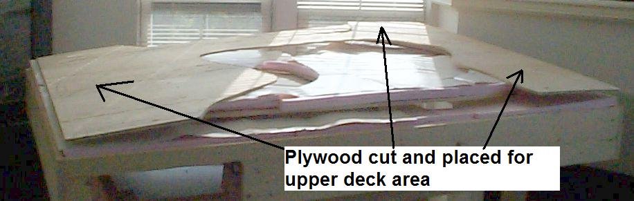
Next the top deck plywood is cut out and placed on the layout.
Supports are added for the upper deck (photos 27, 28, 29 and 30).
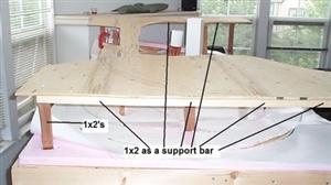
Holes are made in the foam so that the bottom of the supports touch wood. They are glued in place to the plywood below. Also they are glued and screwed (1 1/4 inch screws) to the top plywood piece.
In photo 30 you can barely see a 1x2 across the upper deck. It is glued and screwed (1 1/4 inch screws) in place to provide support for the upper deck. Otherwise it will sag very badly.
Photos 31 to 37 is a sequence of photos showing the way I glue foam to plywood and also foam to foam.
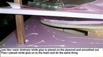


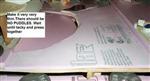
When putting the glue on the wood just spread some on the wood and press the foam on to it. The wood will absorb the glue and make it stick to the foam. When gluing foam to foam however, you should make sure when you do this that the glue is spread very, very thinly. You don't want any puddles at all. It will dry very fast so check to see when it is tacky with your finger. When it is tacky press the foam onto the foam.
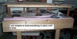
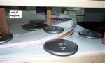
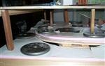
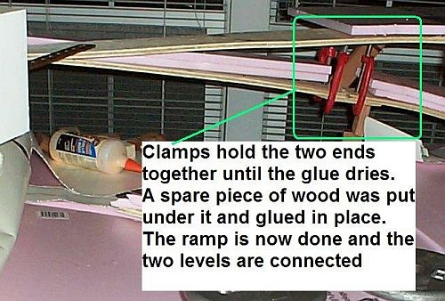
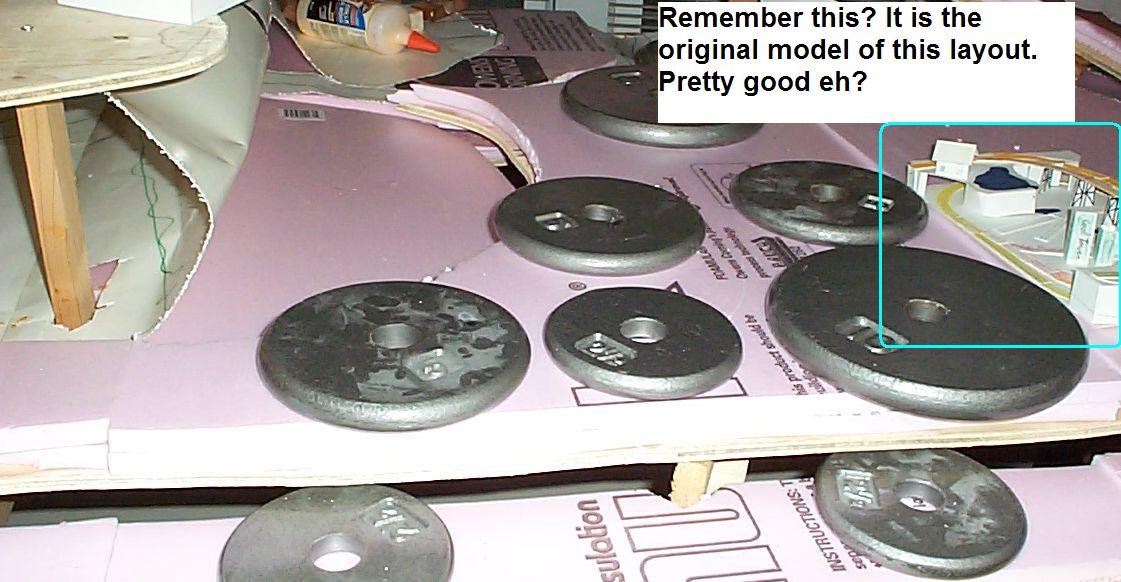
Next add weights. I use ten pounds down to 2 1/2 pounds. Sometime the foam wants to push up because of the hills and such on the layout. Even on a flat layout you should use weights. For the hill connecting the upper to the lower deck. I connected the pieces together and cut them both at the same time so that they were even. The lower deck going up was cut an inch too long on purpose. Then I took a scrap piece of plywood, glued it to the bottom to connect the two decks then I clamped them in place. I will leave it over night to cure.
In photo 39 you can see the original model we made. On the model you can (hopefully) see how it came together on the real thing.
Got a new toy.
It is a bandsaw that hopefully I can use to make wood pieces for my layout to make structure etc.
UPDATE: Well the bandsaw turned out to be crap. I have been warned about Ryobi products for years, but I figured that the thing should be able to cut a straight line in thin wood. I was not expecting it to do anything heavy duty. It could not even cut a straight line. It would be like having a drill that couldn't make holes. Now before you start telling me I should lower the top fence guard, or set the blade bushings to within 1/64th of an inch, or the side brushes, or the bottom parts be adjusted, or tension the blade, etc.
I did all of that and then some. I used their fence, I used a homemade fence. I tried it freehand and still the blade was all over the place. Like I said, I have been warned (even by the store staff by the way) that Ryobi is crap and sure enough it is. A funny thing is that while in line to return it there were about 5 of us and here were more people returning Ryobi products. Considering the thousands of things Home Depot sells I find it significant that the majority of returns, while I was there, was Ryobi.
Interesting eh?
Anyhow, I ended up doing some cutting by hand, more on that later.
I also got the drawer done as well. I made it from scrap pieces so it looks pretty rough, but it works.
Well I hope you have enjoyed this so far. I need to do some more work so see ya all later.
©2009/2020, Josh Baakko, https://www.modelrailroadtips.com